


Originally posted on Dave Mac’s Window on the World: In an amongst the guitar building I decided to break out the soldering iron to build an …
A DIY valve overdrive pedal
Originally posted on Dave Mac’s Window on the World: In an amongst the guitar building I decided to break out the soldering iron to build an …
A DIY valve overdrive pedal

Welcome back to Mod Garage. After receiving numerous requests to show more DIY tools for guitarists, today we’ll explore one of my favorites. For years I’ve used this one in the shop daily and I’m sure you’ll love it. It’s cheap and easy to build, but very effective for analyzing circuits of electric guitars and basses without opening the electronic compartment or lifting the pickguard. It’s a kind of adaptor or extension to measure a pickup’s DC resistance (DCR) from outside the guitar. After building one, we’ll discuss how to interpret the measurements.
The DCR of a pickup is by far the most common parameter you can read when reading pickup descriptions and often it’s used as an indicator of the output. The reason for this is that it’s easy to measure, but, sadly, it doesn’t tell us anything about a pickup’s output nor its tone. To quote pickup designer Bill Lawrence: “DC resistance tells you as much about a pickup’s tone and output as the shoe size tells you about a person’s intelligence.”
I’ve written about DCR as a pickup parameter in detail and you can read about it in “Mod Garage: Demystifying DCR.”
DCR is not a primary parameter in pickup design. It’s simply the result of the type and gauge of the pickup’s wire, the number of turns, and other parameters like the winding pattern, etc. But it isn’t completely useless, and we can use it as a good reference point for analyzing pickups both inside and outside a guitar or bass circuit. All you need for this is a digital multimeter (DMM). You don’t need an expensive calibrated precision DMM—any entry level DMM will work. You can get a simple digital DMM for $10, but if you want to invest in a better device, it can’t harm.
The easiest way to analyze a pickup is outside a circuit. Simply set your DMM to ohm and connect the two pickup leads to your DMM. If your DMM doesn’t have an auto-range function, set it to 20k ohm. Now you’ll get the DCR reading for your pickup. You can compare it to the factory specs of your pickup and it should be close. If your DMM shows “infinite” or “overload,” you know the pickup wire is broken. Let’s say your pickup should read 7k ohm, but yours reads around 2-3k ohm. Your pickup likely has a short circuit somewhere in the winding. Used this way, the DCR is always good to quickly check if a pickup is alive or not.
To quickly analyze a guitar or bass circuit with one or more pickups, you first need to build the DIY adaptor tool this column is about. There are two different versions, and you don’t need much for this:
So, heat up your soldering iron and let’s get to building version #1.

Version #2 is built the same way, but, instead of alligator clips, you solder a 4 mm banana plug to each end of the two wires, if possible, also in black and red. The two wires should be long enough that can place your DMM and/or scope at some distance from the guitar. In Photo 2, you can see version #1 on the top and version #2 on the bottom.

The difference between the two versions is that with version #1 you put the plug into the output jack of the guitar, connecting the two probes of your DMM to the alligator clips: the black probe of the DMM goes to ground (black wire) and the red probe goes to hot (red wire) as seen in Photo 3. With version #2, you need to remove the two probes from your DMM, plugging the two banana plugs directly into your DMM or your scope, also seen in Photo 3.
Both versions work equally well. Version #2 is just easier to operate when you also want to use the adaptor for a scope.
For a quick check, you can also directly touch the hot and ground terminals with the probes of your DMM, but you need both hands or a second person for this if you want to play around with the controls or the pickup-selector switch.
Now we can easily check four things with this tool, assuming everything is connected the way it should be and your DMM is set to ohm and auto-range or the 20k ohm scale if your DMM doesn’t have an auto-range mode:
There is a lot to discover from just the outside of any guitar or bass. So, now let’s see what we can measure from outside the instrument starting with a Telecaster with a 4-way switch. The readings in all examples are the readings I received with guitars I had in the shop, but they can be different in your instruments:
The readings for both pickups are within the factory specs and are in a typical range for a vintage-flavored Telecaster pickup set. With a reading of 3.18k ohm for both pickups together, you know that both pickups are in parallel. With the reading of 12.30k ohm, you know that both pickups are in series with each other.
Here is the simplified math behind these readings:
Now let’s repeat this with a standard Stratocaster:
All three pickups are within the factory specs of this Strat. We have a slightly hotter bridge and two vintage-flavored pickups. The two in-between positions are in parallel.
Lastly, let’s try a vintage PAF-loaded Les Paul:
Both PAFs have the typical vintage DCR and are in parallel in the middle position.
That’s it. Next month we’ll take a deeper look at changing wires on pickups, which is something I’ve been asked about a lot, so stay tuned!Until then … keep on modding!
by Dick Wacker – PREMIER GUITAR

It’s a long-standing debate about what the standby switches on Fender amps are used for. That’s why Sweetwater‘s own tube amp expert, Greg Bowers, decided to clear things up and end the debate once and for all. This is his story más o menos a few Fomedits:
The myth about the lowly standby switch on guitar amplifiers has gone on since they first came on the scene in the 1950s, so no wonder it is still misunderstood. You would think that by now with the internet around everyone would be up to speed, but the myth is too enduring! I have even read articles from educated people that I respect who have not quite gotten the whole story correct because of reasonable sounding, but incorrectly applied details about vacuum tubes. Then the myth gets distorted even more, because everyone thinks these people should know what they are talking about.
These switches are notorious for causing weird problems and numerous questions from my customers like “Why does their amp pop when using it?” (they pop because they are switching anywhere from 300 to 800 volts. WOW!)I have merrily gone on repairing amplifiers over 20 years and decided to break down the mythology of standby switches based on what I know as a technician and amp builder to separate what is folklore and what is fact. At the very least, I would like to explain what standby switches are NOT used for. Here is what I learned repairing amps, doing research and reading history from much smarter people than myself.
Back in the 1940s -50’s there were no books or schools for making guitar amplifiers. Amplifying a guitar was a relatively new idea. Most great guitar amp companies were not founded by textbook electronic engineers or scientists, but smart service technicians who experimented with the recommended RCA vacuum tube circuits already published to get a better sounding or louder amplifier. This is true even to this day.
Designers often push the limits of what a tube can handle to see if it will work past its conservatively rated parameters used for AM radios and Public Address amplifiers. This is kind of like what hot rodder’s do to cars. Special effects using very odd looking devices or circuits also find their way into designs. And yes, there are actual technical mistakes made by these self-trained designers that become accepted norm for a given model. So I learned to expect any reason could be possible for just why standby switches exist!
Historically, I have yet to see an amp made with standby switches until Leo Fender was around. He is accredited for first inventing the idea and I have no reason to doubt this. Leo Fender adopted the standby switch design from reading vacuum tube service manuals. He was self-trained in electronics and developed his own designs. Basically, his switch disconnects the high voltage from the circuit, but the big question is why?
Leo Fender did not intend them for use during beer breaks as a mute switch (the biggest myth of all), even though this is what everyone thought he meant by the “standby” switch label and used them this way! A “mute” switch is a common switch often used on audio amplifiers but never designed the way Leo Fender’s “standby” switch is wired to the high voltage. A mute switch simply connects the audio signal to ground, stopping it from passing through the amplifier, just like turning the volume control all the way down.
One should note the term “standby” has been used occasionally in place of the word “mute” on other switches that actually are audio “mute” switches for taking breaks, further adding to the public confusion. All guitar amplifier companies are infamous for incorrectly labeling or coming up with cute names for a switch’s function. Leo Fender also is known for mislabeling what technically is a tremolo circuit control as a “vibrato”. This is probably because he did not know how to play guitar? Maybe he could have come up with a better name than “standby” that is less confusing? Too late now…

Leo Fender did not use the standby switch to protect the tubes, because it actually is not good to have the tubes on a very long time in standby, which is a fact from the RCA tube manuals. There are so many people who get this part wrong. Beware advice given by some internet guru who was just regurgitating someone else’s myth that sounds technical, but is just wrong!
This myth started with a misunderstanding of the old RCA tube manual recommendation for using standby switches when running very, very high voltage radio station transmitter tubes. RCA was NOT talking about the tubes used in a guitar amplifier. The tubes used in guitar amps are the same type tubes used in Grandma and Grandpa’s old tube radio receivers, TV’s and record players, etc., which you never see with standby switches, do you? Therefore, why would a guitar amplifier be different than these other devices? Because they are not! Fender’s first “Tweed” amplifiers also did not have a standby switch!
For Leo Fender, tubes were cheap back then and actually made much stronger than tubes we have today, so why would he have this supposed concern for tube life? In order to get the tone he wanted, many of his designs are actually very hard on tubes pushing the limits of their power capabilities, therefore it stands to reason that tube life was not his concern.
The standby switch on a Fender amp was put there by Leo to solve a problem he had later when building the much demanded larger power amplifiers using higher voltages to operate.

As the public asked for louder amplifiers, Leo Fender began to build amplifiers with higher power supply voltages. When first turning on the amplifier and before the tubes are warm, tubes do not conduct high voltage, so there is no “load” on the power supply. This phenomenon would allow voltage to rise above the maximum voltage rating for the large capacitors used in the circuit, putting them at risk of shorting out from the stress. This was especially true when Fender started to use solid state rectifier diodes that provided power supply voltage instantly when the mains power was turned on.
While the tubes are warming up, the standby switch removed the high voltage from the circuit until the tubes filaments were warmed up to operating temperature and the power supply voltage would be loaded down by the tubes to the nominal safe operating voltage for the capacitors.
Sure, Leo could have installed much higher voltage rated capacitors that could safely handle the voltage rise, but these were very expensive back in his day. His company’s goal was to produce high quality, but lower cost amplifiers (and guitars), so keeping the price down was important to him. Therefore, the standby switch was a cost-saving design feature much cheaper than the alternative very expensive capacitors.

In my experience, if you want your tubes and the other parts of the amplifier to last longer, put a small fan on the amplifier to get the heat out of it. Excess heat is the greatest problem, so only have the amp on when you need it. Let’s review the takeaways.
There are occasionally a few modern amplifier designs that are taking the problems with conventional plate voltage standby switches into consideration and have put in safer systems for tube warm up purposes. To be fair, these systems do not cause the same potential problems as the old fashioned standby switches. If you have one of these amps, the use of the standby switch may not be causing any harm. You will simply have to inquire about your amps features to know what is used.
However, I still refer to other much smarter engineers than I, including the RCA tube manual which do not list any standby switches in the recommended design of receiving tube power supplies. Don’t expect your tubes to last longer using them.
Don’t use it as a “beer break” switch. For short breaks, simply turn down the volume control (or mute switch if you have one) and don’t use the standby switch, so there is not that nasty pop in the house sound system that could damage speaker drivers. If the time between sound check and performing is longer than 20 minutes, turn the amplifier completely off. You only need 5 minutes at the most to completely warm up a tube amplifier.
It’s as simple as that. Why else would you use something that often pops loudly in the audio when used (remember I mentioned it cuts off the high voltage)? By the way, other brands did not use standby switches until Marshall copied Fender’s Bassman amplifier design and after the two biggest makers used these standby switches, everyone assumed you always had one on a guitar amp. Often, designers put these on amplifiers only because the public asks for them, not that they are needed. This is due to the power of the myth! These days we have other devices available to protect the capacitors and in general capacitors are much cheaper now and can be made to run at higher voltages without great cost.
Don’t put one on your amp because you were told it makes the tubes last longer! Is there a way to help my tubes last longer you say? The correct understanding of vacuum tube operational specifications prove there is no evidence that a standby switch can make your tubes last longer and actually could only hurt them if you overuse the standby mode.
 Seeed Studio miniature soldering iron
The Chinese company Seeed Studio offers a lot of interesting things for electronics enthusiasts. Along with selling products from various manufacturers, Seeed develops and produces their own products, many of which are very innovative. For instance, a year ago we had a close look at the DSO Nano V3 miniature oscilloscope.
Seeed has also developed their own miniature soldering iron, which is now available in a European version. The unique thing about this soldering iron is that a display and the control circuitry are integrated into the grip. From the photos and Seeed’s description, it looked like a good idea for us to get our hands on one and try it out in the Elektor Labs.
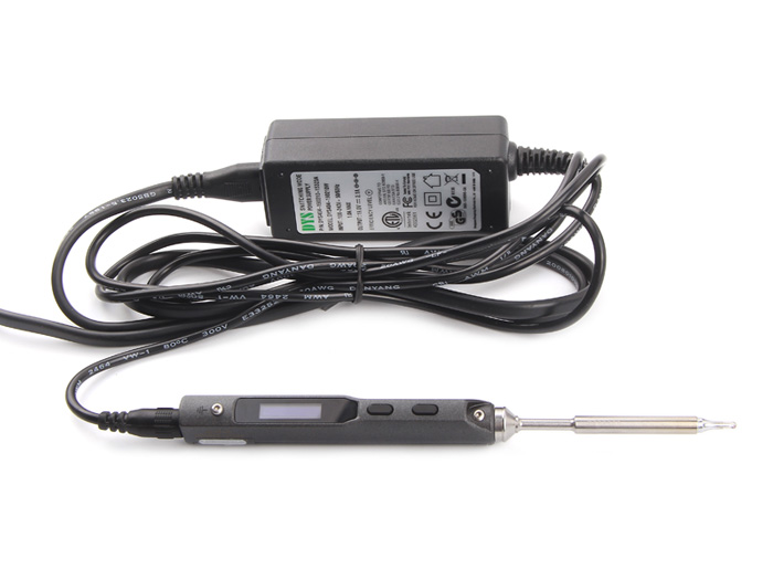
Along with the soldering iron and the associated tip and AC power adapter, the box contains a power cable, a grounding wire with a clip’, an Allen wrench and some spare tips.
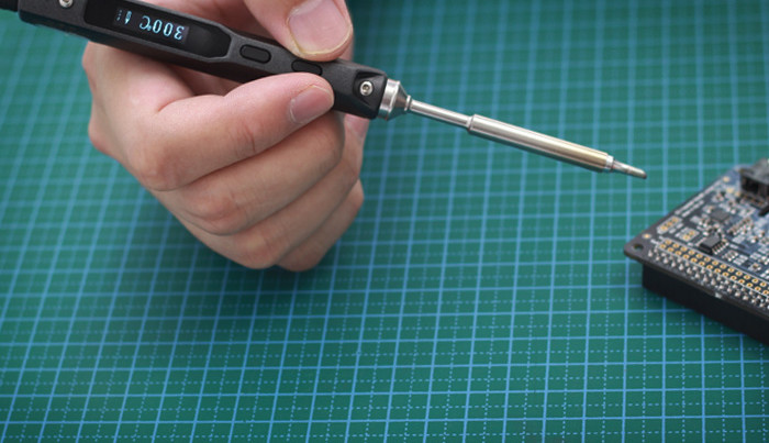
The miniature soldering iron is compact (16.8 x 1.65cm) and looks more like a fat fountain pen than a soldering iron. The grip is made from plastic with a sturdy feel. A small OLED display and two pushbuttons are located on the side of the grip (or is it the top?). The tip slides into the front of the grip and is secured by tightening a small screw with the included Allen wrench. At the rear of the grip there is a power connector and a micro-USB connector for connection to a PC. The soldering iron has a rated power of 40W with the included AC power adapter. You can optionally connect a higher-capacity power supply (max. 24V). That boosts the power to 65W.
After you switch on the power, some messages initially appear on the OLED display, and after you press one of the buttons the preset temperature of 300˚C is displayed. The display is small but easy to read, but unfortunately the information on the display cannot be flipped for left-handed users. The miniature iron heats up quickly – the temperature rose from 20˚C to 300˚C in about 15 seconds. You can use the two buttons to select a different temperature (up to a maximum of 400˚C), but unfortunately the selected value is not saved for the next time you use the iron. If the iron is not used for three minutes, the control circuitry reduces the temperature to 200˚C and the iron remains in sleep mode until it is moved again (apparently it has an integrated motion sensor).The soldering iron is small, light, comfortable and easy to use. The power cable could be a bit more flexible, but that is of course difficult to change when you use a standard AC power adapter. We also did not test the power cable for heat resistance, which is a standard feature with a normal soldering iron. The included soldering iron tip has a fairly fine point and is suitable for most typical soldering tasks with leaded components. It can also be used with relatively large SMD components, but for finer work a tip with a narrower point would be desirable.The iron can also be connected to a computer through a micro-USB cable. The computer recognizes the soldering iron as a USB drive containing a file with the name CONFIG.TXT. After opening this file in Notepad, we saw a number of lines of text with various settings for operating temperature, standby temperature, wait time for standby and some other parameters. These values can be changed and then the file can be saved, after which the iron will use the new values the next time. The software is open source, so you could also modify or extend it as desired.This miniature soldering iron is very handy as a complement to your regular soldering iron. It is small and easy to take with you. The soldering performance is very good, and on top of that you can program it according to your wishes. With a price of around 100 euros, the iron is not exactly low-cost, but when an Elektor designer says he would like to buy one for home use, you know it’s worth the money.