WP QUADS PRO

Park Jihyo

the early talent and skills of Park Jihyo, known mononymously as Jihyo. Jihyo is a South Korean singer and dancer. She is the leader and vocalist of the South Korean girl group Twice, formed by JYP Entertainment.

the role of the capacitor in music

the capacitor

capacitors

In the realm of passive components, capacitors are second only to resistors in ubiquity. They are everywhere, in almost every electronic device you will ever come across. So it’s no surprise that capacitors are an integral part of audio circuits in general, and guitar effects specifically.

What makes capacitors so important? Well, they can be used to perform some very important functions:

  • DC Blocking:Capacitors pass alternating current (AC), but block direct current (DC)
  • Coupling: Capacitors are used in between various stages in audio circuits
  • Filtering: Capacitors are key elements of filters, such as a tone control
  • Smoothing: Capacitors are used to smooth out ripples and noise in power supplies
  • Timing: Capacitors are used to set the timing of circuits such as low frequency oscillators
  • Storing: Large value capacitors are used to store up energy. For example, the flash of a camera typically uses a capacitor to store and quickly discharge amount of power

Units of Measure

As with all passive components, you need to have a basic understanding of units of measure when working with capacitors. Capacitance is measured in Farads, named after English physicist Michael Faraday. A value of 1 Farad is actually quite high, so we use sub measures as follows:

SymbolNameEquivalence
μFmicro1,000,000μF = 1F
nnano1,000nF = 1μF
ppico1,000pF = 1nF

If you are like me, the concept of base 10 arithmetic is wildly advanced and causes your head to hurt. So I invariably turn to the awesome online and downloadable calculators from http://www.electronics2000.co.uk for doing unit conversions.

Capacitor Types

Although capacitors come in an almost bewildering array of types and sizes, no need to worry. The majority of capacitors in guitar effect designs fall into three types:

  • Electrolytic: Usually for large capacitance values, typically 1μF and above. These are usually polarized, meaning there are positive and negative leads.
  • Film: The most commonly used types, typically in the range of 1nF to 999nF. These are non-polarized and can go in either way.
  • Ceramic: Used for smaller values, typically from 10pF to 999pF. As with Film capacitors, these are non-polarized.

With these basic types in minds, let’s learn a bit more about each.

Voltage Rating

One of the most common questions about choosing capacitors is voltage rating. Different capacitors are rated for different voltage ranges. The best rule of thumb is to choose a capacitor with a voltage rating that is at least twice the operating voltage of your circuit. So if you are building a circuit that runs of 9 volts, choose capacitors with ratings of at least 16 volts.

Electrolytic Capacitors

Electrolytic capacitors are visually distinguished by their ‘can’ form factor. They are commonly used in power supply filtering and decoupling applications. They are usually polarized which means that they have a positive side and a negative side. (See “Non-Polarized Electrolytics”below).

Electrolytic capacitors come in several physical configurations:

axial capacitorsAxial: There are leads coming out either end of the cap. Typically mounted parallel to the board.
radial capacitorRadial: Both leads come out of one end. Typically mounted vertical to the board.
snap-in capacitorsSnap-In: For larger electros, not recommended for DIY stuff because they lack the long leads that make it easy to fit them to a board.
smd capacitorsSMD: Surface mounted device, which are designed to be assembled/soldered by automated devices. Not so user-friendly to human solderers.

The polarity of the electrolytic capacitor is almost always indicated by a printed band. Additionally, the positive lead is usually longer.  

When working with electrolytic capacitors, here are a few things to keep in mind:

  • Polarity: Most electrolytic capacitors are polarized. Hook them up the wrong way and at best, you’ll block the signal passing through. At worst (for higher voltage applications) they’ll explode.
  • Getting Shocked and Possibly Dying: This is not usually a concern for low-voltage stompbox applications, but for high-voltage circuits, especially tube amplifiers, big electros can hold a charge for quite a while. Before you open up anything that plugs into the wall, google capacitor discharging and approach with caution. See ;Capacitor Fires and Explosions” below.
  • Radial vs. Axial:To maximize the real estate on a PCB, you’ll almost always want to use radial leads. When you order caps, get the radial ones. If you order Axial by mistake, it isn’t hard to bend the leads so as to mount them in a radial, upright configuration.
  • Non-Polarized Electrolytics: To further confound you, electrolytics are made in non-polarized versions. These are rarely used. The only place I’ve seen them is on either side of the first opamp stage in the Tube Screamer.

Ceramic Capacitors

ceramic capacitors

Ceramic caps are typically used for lower capacitance jobs. Values are usually in the picofarad to low nanofarad range. They are ugly looking, and that is about as technical as I’ll get on the whole ceramic vs. film caps debate.

Most folks cannot discern an audible difference between the two types in common stompbox use, so you’ll have to try for yourself. A good rule of thumb is to remember that from an electrical engineering standpoint, film capacitors are generally preferred over ceramics in audio path applications. Ceramics are non-polarized and usually supplied in the radial lead configuration.

The Great Tantalum Debate

Tantalum capacitors were popular in the eighties in stompbox designs like the Ibanez Tube Screamer and various MXR and DOD designs. The primary benefit of tantalums is that they offer a higher range of capacitance values in package that is physically smaller than electrolytics.

Like electrolytics, they are polarized so you’ll want to get the direction right. Tantalums are *very* susceptible to polarity inversion. In other words, if you hook one up backwards you might as well throw it away–there is a good chance it is cooked.

Do they sound better? Do they sound different? The answer is a definitive yes. No wait, that’s a definitive no. There are many opinions about tants, so I really cannot offer you anything definitive on this subject. I can however, share some of the feedback and comments I’ve heard and read.

  • Replace place all electrolytic caps in the signal path with tantalums for a smoother sound.
    Some folks hear more “grit” and treble with tantalums. Some hear a smoother sound.
  • Replace the .022 tantalum in your tube screamers with a poly film part for better sound, others claim the original part is integral to the true tube screamer sound.
  • Some folks claim tantalums are not as reliable as electrolytics, but this may be mostly due to older composition and packaging types uses in decades past.

As always, your mileage will vary. But this is one of the most wonderful areas of stompbox design–there are so many variations, we’ll probably never get bored. Try the variations yourself until  you find your ideal sound.

Capacitors on the Fringe

There are various esoteric or rare capacitor types that pop up from time to time.

Tropical Fish Caps

These are vintage poly film capacitors that use color codes to denote the capacitance value. Very rare nowadays and expensive too. Some builders like to use them in vintage circuits,especially wah pedals.

The Wima Audio Black Box Audio Cap

Rare, elusive and really expensive. I don’t have much info on these, but some audiophile people swear by them.

Wet Tantalums

Most tantalum caps are of the dry-slug variety. This means that they are composed of dry tantalum powder. Wet-slug tantalums on the other hand use gelled sulfuric acid. For more mojo, I wonder if wet-slug tantalums would be worth trying. Although they are typically used for high temperature and voltage applications, one has to wonder…

Audiophile Parts

In the world of DIY audiophile building, a great emphasis is often placed on capacitor performance. As a result, there are a number of manufacturers of high-end (and expensive) capacitors. I’ll leave the subjective vs. objective argument to the reader. But it does make sense to point out that guitar effects, especially in stompbox format, are not designed to be audiophile devices.

Which Type Should I Choose?

As with all component types, there are pros and cons for each type. In general, the choice of capacitor type will be made for you, either by the author of the schematic you are using, or by the simple factor of capacitance value. In other words, the schematic will specify electrolytic or film by the symbol used. That makes the choice easy.

But what about when a specific type is not specified, only the value is shown? In general, you look at the value specified, and choose the type appropriate for that value. Other factors may influence your choice of capacitor type, particularly in audio circuits. So I’ve include benefits and drawbacks of each type.

Capacitor TypeTypical Value RangeSchematic SymbolBenefittsDrawbacks
Electrolytic>= 1μF
⎯)|₊⎯
Higher capacitance values in smaller packages, Reasonable priceLeakage is higher than most types, service life: Electros typically don’t last near as long as other types. This is typically why tube amps need to be re-capped after a number of years. Tolerance is not great: most passive electronic components have a tolerance rating which denotes how close to the part is to the actual printed value. Tolerance for electrolytics is abysmal, in the 20-40% range, but for stompbox applications, this doesn’t matter.
Film1nF – 999nF⎯||⎯̇Low leakage and they last a long timeLarger values are inordinately physically large
Ceramic1pF – 999pF⎯||⎯InexpensiveFilm caps are usually preferred to ceramic caps where audio performance is a key design factor

Capacitors on Schematics

Here’s what capacitors look like on schematics:

What about Variable Capacitors?

One of the first questions I had when I started building stompboxes was “I have variable resistors (potentiometers) all over the place. Why don’t I have variable capacitors?” The answer is that they are limited to a very small capacitance and are quite expensive too. As such, they are not practical for stompbox usage.

Here’s a trick to simulate a variable capacitor, especially useful for tone control applications. Attach two different capacitor values to a potentiometer–moving the wiper then sends more or less of the signal to one of the caps thereby changing the frequency response.

Capacitor Fires and Explosions

Like other components, capacitors can explode, burn, and/or stink when they are voltage-abused. Here are some fun fire and explosion pictures. Note that many capacitors were harmed during these experiments.

Some builders have intimated that tantalum capacitors smell the worst when on fire. This is a very useful piece of engineering knowledge to have.

The Application of Capacitors in Stompboxes

So now we are familiar with the basics of capacitors, how can we use them in stompboxes? In a surprisingly large number of ways actually.

Power Supply Filtering

In the context of stompboxes, power supply is a low voltage (usually 1.5-18 volts) direct current. The battery is a pretty ideal power source for stompboxes. As long as the battery isn’t dying or depleted, it doesn’t fluctuate wildly or introduce DC ripple into the equation. So if you are running solely on battery power, you really don’t need to worry much about filtering.

Power supplies, like the ubiquitous unregulated black wall warts on the other hand aren’t so ideal. If you are sure that your stompbox design will only ever see external voltage as supplied by a nicely regulated and filtered AC adaptor, then you don’t need to design in filtering. But in the real world, such assurances are not available. You have to assume that at some point you (or the person you build stompboxes for) will plug in a cheap nasty Szechuan special and noise and nastiness will result.

Of course, it is interesting to note that many stompbox schematics will include no filtering at all, and for the majority of uses, that is actually ok. Filtering really becomes an issue when your circuit is presented with a crappy power supply or fluctuating “crazy Ivan” mains voltage.

A wall wart uses a transformer to step down the mains voltage to a pedal friendly 9-11 volts or so (for a 9v adaptor) and then converts AC into DC using a 4-diode bridge rectifier. The rectifier flips all the waveform swings of the AC voltage but still results in some “ripple” in the DC waveform. Ripple equates to noise in your circuit. The simplest way to get rid of this ripple is to tack a largish-value electrolytic cap from the power supply to ground to smooth things out. For most stompbox designs, this works just great. Let’s look at an example.

Here we simply add a 100uf polarized electrolytic from the power supply line to ground to reduce ripple:

Finally, there is an additional electrolytic on the bias voltage (C3) which smoothes out the bias supply.

A parting note on caps in power supplies. For amplifier circuits, you’ll see big electrolytic cans in the power supply section that you don’t see in stompboxes. These act as “reservoirs” of current to handle short spikes in power demands from the amplifier and to smooth out the available pool of current.

The Input and Output Caps

Almost every stompbox design has these two caps. As we talk about these, keep in mind the following schematic of the Electro Harmonix LPB booster (I’m using this one because it has input and output caps and is about as simple a circuit as you can find.)

The input cap (C1), if you haven’t already guessed, is attached at or very near the input. The purpose of the input cap is to form a high-pass filter, in conjunction with a resistor (here the R2 part). It also acts to stabilize the rest of the circuit from the input which is usually a guitar, bouzouki, or another pedal. The key point here is:

The value of the input cap directly controls any frequency attenuation that happens before the signal hits the main effect circuitry.

Now on to the output cap. In our schematic above, that’s the C2 value. The output cap serves two purposes. First, like the input cap, it can serve as part of an RC network to attenuate or pass certain frequencies. If you want the full frequency range, a value from 100nf to 1uf can be used. The output cap also serves to remove any direct current from the signal. Remember that our stompbox designs almost all run on direct current–we want to be sure none if it escapes from the output jack, so an electrolytic cap will do the job nicely.

Input and Output Capacitor Values from Various Classic Stompbox Circuits
CircuitInput CapOutput Cap
Ibanez Tube Screamer.027uf film10uf electrolytic
ProCo Rat22nf film1uf electrolytic
Boss DS-1.047 film1uf electrolytic
Dallas Rangemaster.005uf.01 uf film
Dallas Fuzz Face2.2uf electrolytic.01 uf film

Let’s say you are building a treble-booster–you would want to attenuate any low frequency content before it hit the amplifier circuit. So you would put in a lower value input cap to accomplish this. The Dallas Rangemaster, perhaps the most famous of all treble boosters, has an incredibly small .005 uf cap.

Another great example of the effect of cap values on frequency response isa href=”http://folkurban.com/Site/LofoMofo-724.html”>Tim Escobedo’s LoFoMoFo. Look at the very small values for the input, output and shunting caps (R1, R3 and R2, respectively). These parts conspire to remove pretty much all the bass content of the input signal:

Alternatively, let’s say you want the majority of the useful frequency content to be passed through–in this case you would use a larger value cap, say 100nf-1uf. A rule of thumb is that a 1uf capacitor, input or output, will allow all guitar frequencies to pass through.

Filters

Variable Low-Pass Filter

Here we use a small value cap (500pf up to 50nf is a good range for experimentation) wired in the signal path of a circuit. If the pot’s wiper is at the full open position (no resistance) the signal will bypass the cap and go straight through. But as the resistance is increased, more signal will pass through the cap which will attenuate higher frequencies.

Another way to implement a low pass filter is to used a potentiometer in series with a capacitor to ground. This type of configuration can be spliced into the signal path of a circuit, but it should be noted that there is some signal loss. This is the case with all such passive circuits. Usually, there is a gain stage after a passive tone control to boost the signal lost in the passive section. For example, look at the last transistor stage in the Big Muff Pi circuit: it’s function is to make up for the signal loss in the preceding tone control.

Smoothing Diode Clipping

You can add a small-value capacitor in parallel with a diode clipping arrangement to smooth out the high-end of the clipping. This is a somewhat interesting area for experimentation.

Capacitors for Timing

Another common use for capacitors is to control the time interval of a circuit. For example, in a low-frequency oscillator, a capacitor is used in conjunction with a potentiometer to set the frequency. Our first example is a simple LFO based on the 40106 Hex inverting Schmitt trigger. The combination of C1 and VR1 set the frequency:

Next, we have a classic 555 basic monostable oscillator. In this configuration, the frequency is set by a combination of R1 and C1.

LISA [lalisa] of BLACKPINK : K-Pop Fashion

THE COYOTE SANDBAG


fomtooley coyote sandbag bone bridge guitar acoustic superior the best bone bridge there is classical guitar handmade nut strings string guitar guitars luthier repair replacement real bone handcrafted polished revolutionary new design reduces string breakage and tension and friction for better pure tone the absolute best bone nut you can get buy it now eat ny ass too

The Coyote Sandbag:

When a guy teabags and she bites his nuts to make him howl.

“Man I need an ice pack… This bitch just gave me The Coyote Sandbag!


fomtooley coyote sandbag bone bridge guitar acoustic superior the best bone bridge there is classical guitar handmade nut strings string guitar guitars luthier repair replacement real bone handcrafted polished revolutionary new design reduces string breakage and tension and friction for better pure tone the absolute best bone nut you can get buy it now eat ny ass too

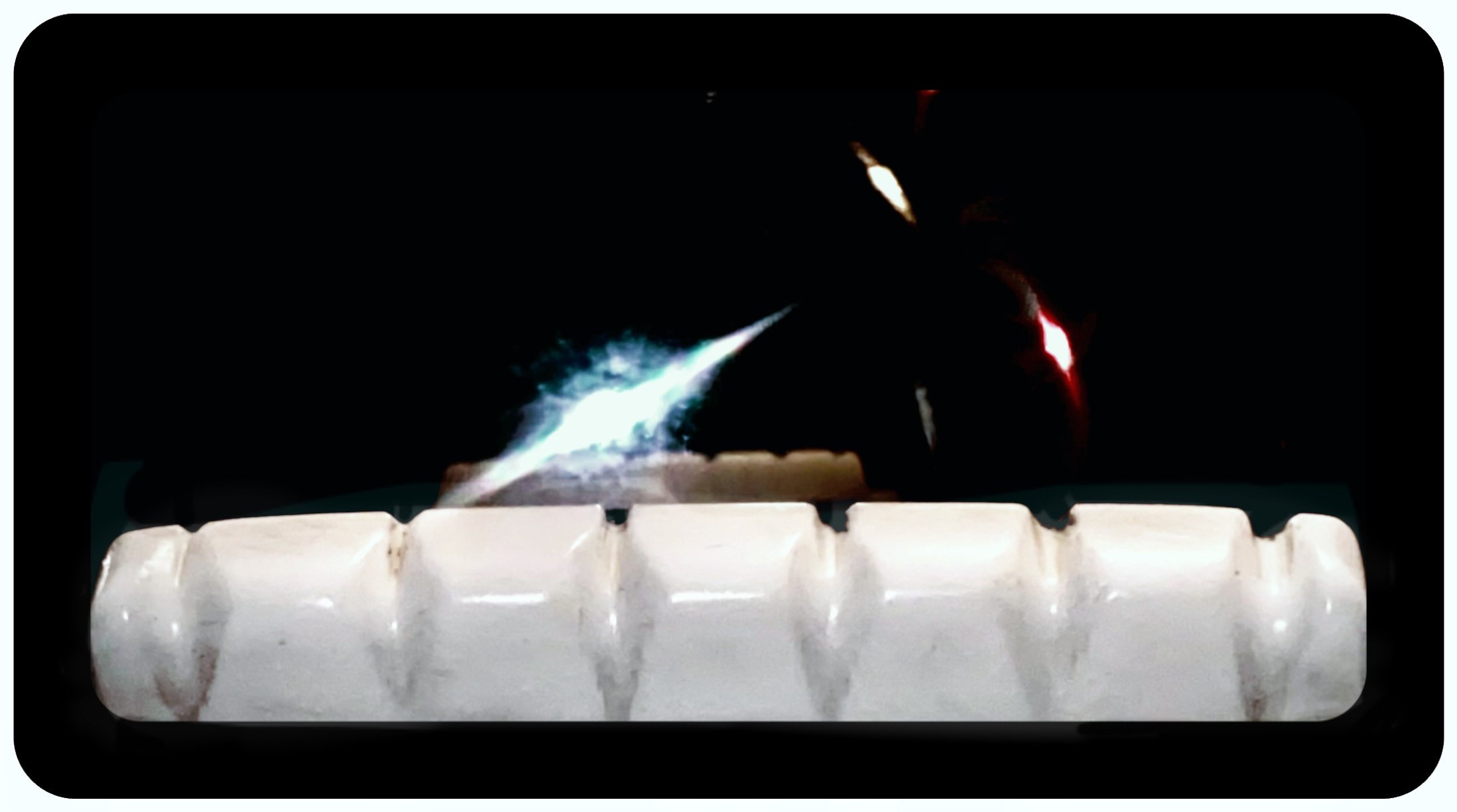
brush them with acid like your teeth


fomtooley coyote sandbag bone bridge guitar acoustic superior the best bone bridge there is classical guitar handmade nut strings string guitar guitars luthier repair replacement real bone handcrafted polished revolutionary new design reduces string breakage and tension and friction for better pure tone the absolute best bone nut you can get buy it now eat ny ass too

handcrafted in the united states, not chinese bullshit


fomtooley coyote sandbag bone bridge guitar acoustic superior the best bone bridge there is classical guitar handmade nut strings string guitar guitars luthier repair replacement real bone handcrafted polished revolutionary new design reduces string breakage and tension and friction for better pure tone the absolute best bone nut you can get buy it now eat ny ass too

boner nut by fom tooley


fomtooley coyote sandbag bone bridge guitar acoustic superior the best bone bridge there is

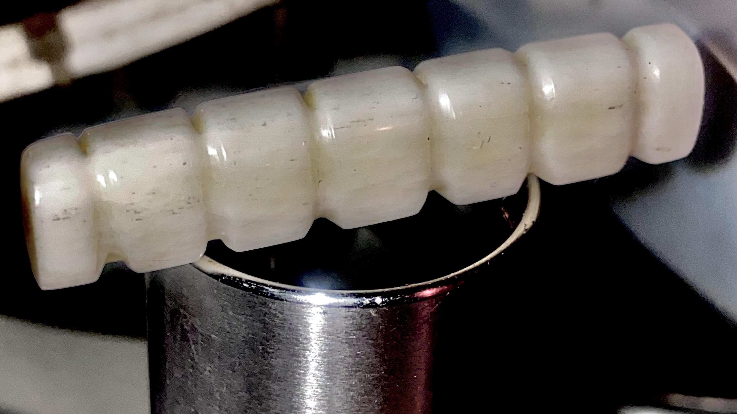
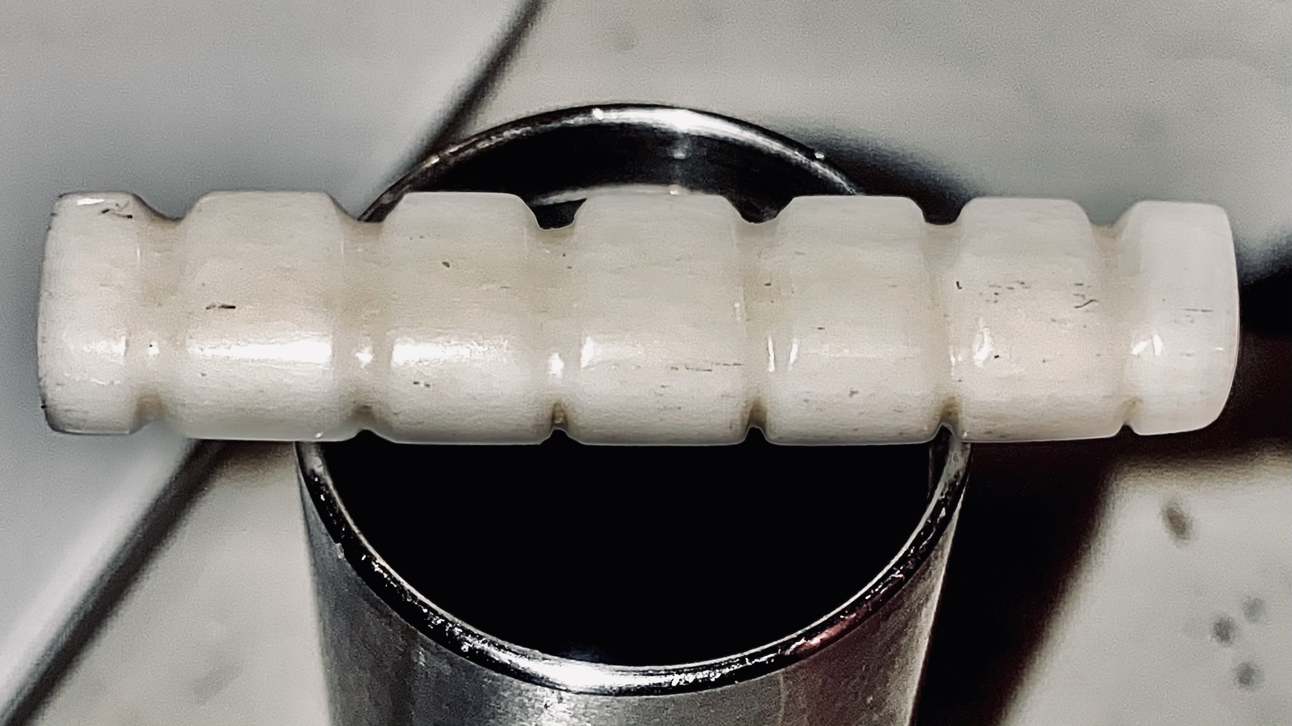
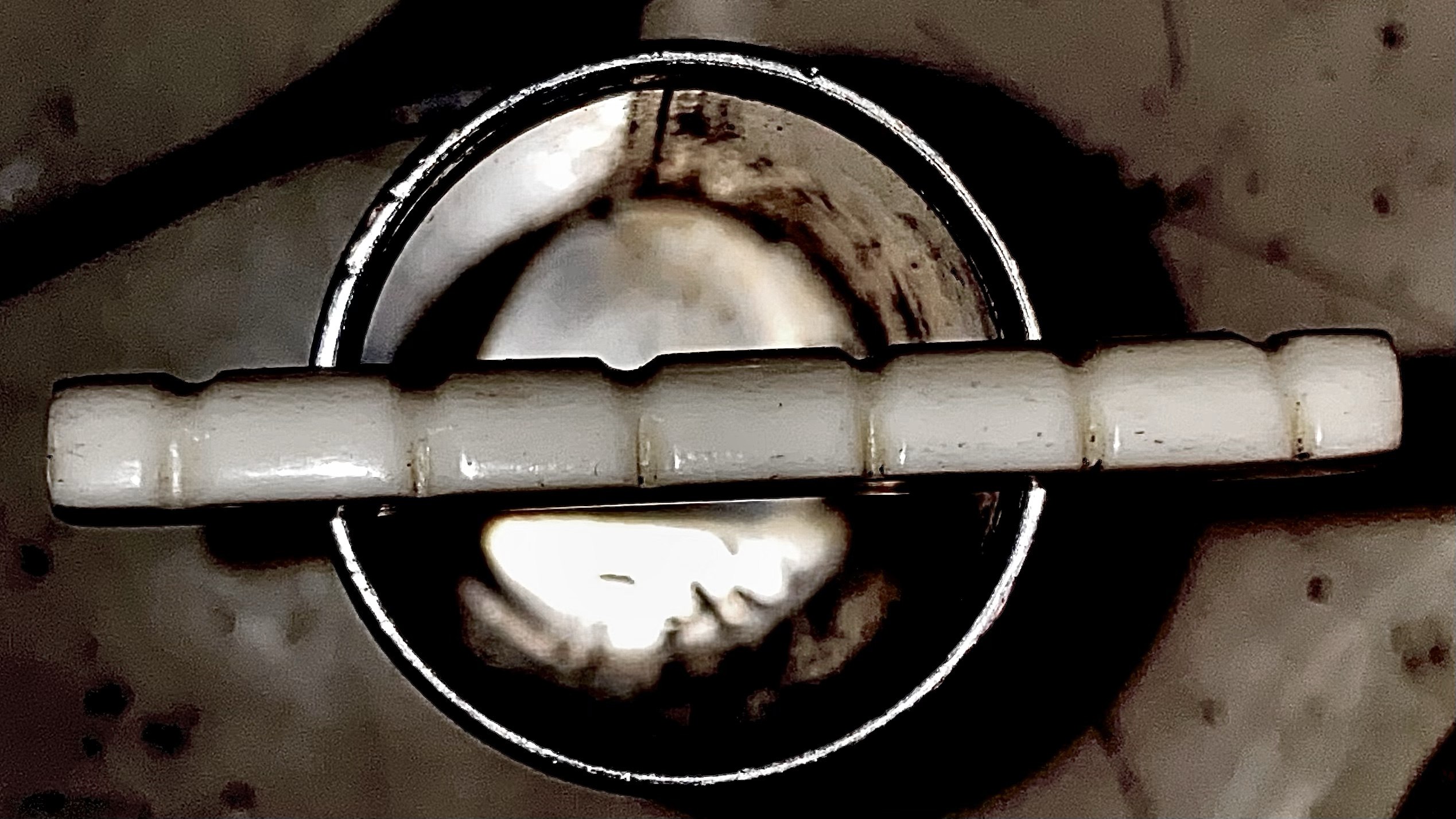
real handmade bone nut for acoustic snd classical guitars


Standby Switch Myth

tube amplifier standby switch information

It’s a long-standing debate about what the standby switches on Fender amps are used for. That’s why Sweetwater‘s own tube amp expert, Greg Bowers, decided to clear things up and end the debate once and for all. This is his story más o menos a few Fomedits:

The Standby Switch

The myth about the lowly standby switch on guitar amplifiers has gone on since they first came on the scene in the 1950s, so no wonder it is still misunderstood. You would think that by now with the internet around everyone would be up to speed, but the myth is too enduring! I have even read articles from educated people that I respect who have not quite gotten the whole story correct because of reasonable sounding, but incorrectly applied details about vacuum tubes. Then the myth gets distorted even more, because everyone thinks these people should know what they are talking about.

These switches are notorious for causing weird problems and numerous questions from my customers like “Why does their amp pop when using it?” (they pop because they are switching anywhere from 300 to 800 volts. WOW!)I have merrily gone on repairing amplifiers over 20 years and decided to break down the mythology of standby switches based on what I know as a technician and amp builder to separate what is folklore and what is fact. At the very least, I would like to explain what standby switches are NOT used for. Here is what I learned repairing amps, doing research and reading history from much smarter people than myself.

Tube Amp History

Back in the 1940s -50’s there were no books or schools for making guitar amplifiers. Amplifying a guitar was a relatively new idea. Most great guitar amp companies were not founded by textbook electronic engineers or scientists, but smart service technicians who experimented with the recommended RCA vacuum tube circuits already published to get a better sounding or louder amplifier. This is true even to this day.

Designers often push the limits of what a tube can handle to see if it will work past its conservatively rated parameters used for AM radios and Public Address amplifiers. This is kind of like what hot rodder’s do to cars. Special effects using very odd looking devices or circuits also find their way into designs. And yes, there are actual technical mistakes made by these self-trained designers that become accepted norm for a given model. So I learned to expect any reason could be possible for just why standby switches exist!

It’s not a mute switch for breaks

Historically, I have yet to see an amp made with standby switches until Leo Fender was around. He is accredited for first inventing the idea and I have no reason to doubt this. Leo Fender adopted the standby switch design from reading vacuum tube service manuals. He was self-trained in electronics and developed his own designs. Basically, his switch disconnects the high voltage from the circuit, but the big question is why?

Leo Fender did not intend them for use during beer breaks as a mute switch (the biggest myth of all), even though this is what everyone thought he meant by the “standby” switch label and used them this way! A “mute” switch is a common switch often used on audio amplifiers but never designed the way Leo Fender’s “standby” switch is wired to the high voltage. A mute switch simply connects the audio signal to ground, stopping it from passing through the amplifier, just like turning the volume control all the way down.

One should note the term “standby” has been used occasionally in place of the word “mute” on other switches that actually are audio “mute” switches for taking breaks, further adding to the public confusion. All guitar amplifier companies are infamous for incorrectly labeling or coming up with cute names for a switch’s function. Leo Fender also is known for mislabeling what technically is a tremolo circuit control as a “vibrato”. This is probably because he did not know how to play guitar? Maybe he could have come up with a better name than “standby” that is less confusing? Too late now…

The addition of standby switches on tube amps is accredited to Leo Fender.

It’s not for protecting tubes

Leo Fender did not use the standby switch to protect the tubes, because it actually is not good to have the tubes on a very long time in standby, which is a fact from the RCA tube manuals. There are so many people who get this part wrong. Beware advice given by some internet guru who was just regurgitating someone else’s myth that sounds technical, but is just wrong!

This myth started with a misunderstanding of the old RCA tube manual recommendation for using standby switches when running very, very high voltage radio station transmitter tubes. RCA was NOT talking about the tubes used in a guitar amplifier. The tubes used in guitar amps are the same type tubes used in Grandma and Grandpa’s old tube radio receivers, TV’s and record players, etc., which you never see with standby switches, do you? Therefore, why would a guitar amplifier be different than these other devices? Because they are not! Fender’s first “Tweed” amplifiers also did not have a standby switch!

For Leo Fender, tubes were cheap back then and actually made much stronger than tubes we have today, so why would he have this supposed concern for tube life? In order to get the tone he wanted, many of his designs are actually very hard on tubes pushing the limits of their power capabilities, therefore it stands to reason that tube life was not his concern.

The standby switch on a Fender amp was put there by Leo to solve a problem he had later when building the much demanded larger power amplifiers using higher voltages to operate.

Don’t leave your tube amp on standby for too long. It’s bad.

The actual reason for standby switches

It’s all about the capacitors!

As the public asked for louder amplifiers, Leo Fender began to build amplifiers with higher power supply voltages. When first turning on the amplifier and before the tubes are warm, tubes do not conduct high voltage, so there is no “load” on the power supply. This phenomenon would allow voltage to rise above the maximum voltage rating for the large capacitors used in the circuit, putting them at risk of shorting out from the stress. This was especially true when Fender started to use solid state rectifier diodes that provided power supply voltage instantly when the mains power was turned on.

While the tubes are warming up, the standby switch removed the high voltage from the circuit until the tubes filaments were warmed up to operating temperature and the power supply voltage would be loaded down by the tubes to the nominal safe operating voltage for the capacitors.

Sure, Leo could have installed much higher voltage rated capacitors that could safely handle the voltage rise, but these were very expensive back in his day. His company’s goal was to produce high quality, but lower cost amplifiers (and guitars), so keeping the price down was important to him. Therefore, the standby switch was a cost-saving design feature much cheaper than the alternative very expensive capacitors.

The standby switch removes high voltage from the circuit while the tubes warm up.

Takeaways

In my experience, if you want your tubes and the other parts of the amplifier to last longer, put a small fan on the amplifier to get the heat out of it. Excess heat is the greatest problem, so only have the amp on when you need it. Let’s review the takeaways.

There are occasionally a few modern amplifier designs that are taking the problems with conventional plate voltage standby switches into consideration and have put in safer systems for tube warm up purposes. To be fair, these systems do not cause the same potential problems as the old fashioned standby switches. If you have one of these amps, the use of the standby switch may not be causing any harm. You will simply have to inquire about your amps features to know what is used.

However, I still refer to other much smarter engineers than I, including the RCA tube manual which do not list any standby switches in the recommended design of receiving tube power supplies. Don’t expect your tubes to last longer using them.

Don’t use it as a “beer break” switch. For short breaks, simply turn down the volume control (or mute switch if you have one) and don’t use the standby switch, so there is not that nasty pop in the house sound system that could damage speaker drivers. If the time between sound check and performing is longer than 20 minutes, turn the amplifier completely off. You only need 5 minutes at the most to completely warm up a tube amplifier.

It’s as simple as that. Why else would you use something that often pops loudly in the audio when used (remember I mentioned it cuts off the high voltage)? By the way, other brands did not use standby switches until Marshall copied Fender’s Bassman amplifier design and after the two biggest makers used these standby switches, everyone assumed you always had one on a guitar amp. Often, designers put these on amplifiers only because the public asks for them, not that they are needed. This is due to the power of the myth! These days we have other devices available to protect the capacitors and in general capacitors are much cheaper now and can be made to run at higher voltages without great cost.

Don’t put one on your amp because you were told it makes the tubes last longer! Is there a way to help my tubes last longer you say? The correct understanding of vacuum tube operational specifications prove there is no evidence that a standby switch can make your tubes last longer and actually could only hurt them if you overuse the standby mode.