Understanding ABY Switchers

introductory photo showing three ABY switchers made by Radial Engineering

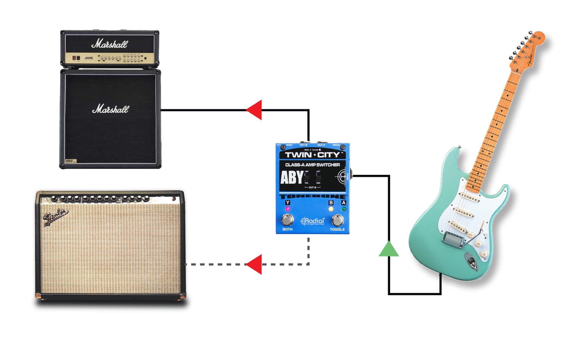
ABY switchers are primarily used to feed two guitar amps from a guitar. The AB designates the ability to switch between amplifiers, while the Y means that both amps can be turned on at once.  Using an ABY switcher is easy. You connect your guitar or the output from your pedal chain to the ABY, and from the ABY, you feed the two amps. Unfortunately, the results often include tremendous noise, weird tones, and even an electrical shock.

diagram showing how an electric guitar can be connected to two amplifiers simultaneously using an ABY switch

passive versus active

ABY pedals generally come in two categories: passive and active. Passive ABYs do not require any power to make them work while active ABYs must be powered like most other guitar pedals.

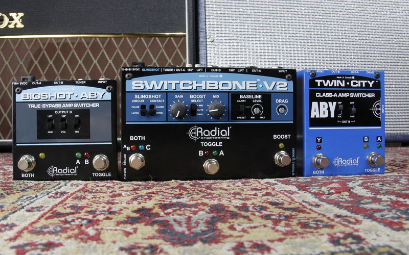
Passive ABYs are simple switches that divert the guitar signal to one amp or the other.  There is no ‘buffer’ or electronic amp inside the ABY to manage the signal. Some tone purists prefer passive switchers as they do not color the guitar signal in any way. When running two amps at once, the signal going to each amp is reduced by half, like a simple Y-jack cable.  The BigShot ABY is a passive ABY switcher.

Active switchers employ a buffer or unity-gain amplifier to lower the impedance to reduce susceptibility to noise and manage the electrical signal. A buffer not only drives the signal further without noise, but the capacitors in the signal path also block noise that may be coming from the amp from bleeding back into the guitar.

true-bypass

Pedals that completely remove the effect circuit from the signal path are known as true-bypass pedals.  The concept here is that a true-bypass pedal will relay the original sound of the guitar without any buffer or loading on the pickup which could alter the clean tone. The downside with true-bypass pedals is that they tend to produce switching noise. This is due to the hard contact that is created when the footswitch is depressed and the internal relay is called into action. The noise is most noticeable when using high-gain amps.

active switching

The benefit to using active switching with a buffered circuit is that it allows the electronic engineer to manage the signal to eliminate noise. The Twin-City employs electronic switching while the Switchbone employs a series of photo-electric chips (optocouplers) that ramp up and then ramp down the signal in a controlled fashion in order to eliminate the hard contact. This type of switching requires the signal to be buffered.

photo of Twin City ABY Class A Amp Switcher by Radial Engineering

Types of buffers

There are two general camps when it comes to buffers. The most common is the use of an integrated circuit (IC) while the second is more of an old-school discrete class-A approach. For maximum efficiency, ICs pack thousands of transistors inside a very small package to produce tremendous gain. To control the gain, various degrees of negative feedback is applied. Most guitarists hate the sound of these buffers as they make a nice warm-sounding guitar sound harsh. This is the primary reason guitarists complain about the sound of wireless systems. Both the Twin-City and the Switchbone employ 100% discrete, class-A circuitry. Instead of trying to control the gain of a chip by applying tremendous amounts of phase-canceling negative feedback, individual transistors are used at each gain stage. This means only the absolute minimal amount of negative feedback is applied. And because we are using class-A circuitry, you get a much purer signal path.

Load Correction

Early on, we discovered that even with the very best circuit, buffering a guitar signal can make it sound ‘too clean’. To solve the problem, Radial invented Drag Control – a simple load correction circuit that compensates for the overly clean signal path and replicates the tone as if connected directly to the amp. This encompasses compensating for the natural roll off of the cable and of course the load that is typically applied from a tube amp – whereby it sounds totally different from a transistor amp.

illustrated example of how an audio ground loop is produced

Ground loops

The hum and buzz caused by a so-called ground loop are produced when two amps are connected together and share both an electrical ground and an audio ground.  The noise problem can be mild to acute depending on the amps, the electrical circuit and other factors such as spurious noise from the electrical system. The first line of defense is to connect both amps and all of the pedals to a single power strip. This ensures the same electrical phase is powering both amps. Unfortunately, more often than not, this solution rarely solves the  problem that is inherent with varying voltage references and grounding schemes on the amps. To solve the problem, transformers are inserted into the audio path.

Transformer Isolation

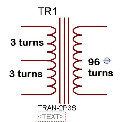
A typical transformer is a device that is made up of two coils and an inner core. The primary or input coil becomes magnetically charged when current is applied. The magnetic field is then transmitted through the core where it excites the secondary coil which in turn produces an electrical current.  This creates a magnetic bridge that passes audio, while blocking stray DC currents and noise. Since the bridge is magnetic, there is no direct electrical connection. This disconnects the audio ground and breaks the ground loop, thus eliminating the hum and buzz. The Twin-City and Switchbone have transformers on output-B for this reason. The BigShot ABY also has a transformer that may be inserted into the signal path. As transformers are passive, you can lose some of the signal going through it unless the signal is first buffered by a pedal.

Phase

When playing two amps, it is important that they both play in phase. This means that both speakers are pushing outward instead of one going in, while the other goes out. When both amps are on, if the sound is distant, the amps are likely out of phase.  In order to phase-align the amps, you must be able to reverse the polarity at the output of the ABY switcher. This requires a transformer.  The BigShot ABY, Twin-City and Switchbone are equipped with transformers and 180º degree phase switches to invert the polarity.

Switching noise

As mentioned above, true-bypass switches are basically hard electrical switches produced by a footswitch or an electronic relay. These do not color nor load the pickup but do so at the expense of a loud pop. This is most noticeable when using high-gain or distorted amps. The BigShot ABY uses a true-bypass footswitch. Electronic switching as used in the Twin-City employs an electronic circuit to do the switching. This buffered circuit allows the engineer to control the switching to eliminate the loud pop. In this case, the buffered signal is always in the signal path. The Switchbone goes one step further by employing opto-couplers that ramp up and down the signal for a super smooth and quiet transition. Opto-couplers employ an internal light and receptor to do the work. These are expensive and rarely used.

Electrical Shocks

To avoid an electric shock, never disconnect the U-ground on your guitar amps. This is sometimes done to eliminate noise. The ground is there for safety and will save your life if ever you find yourself on a wet stage or somehow get entangled in a situation where the power system from the lights or PA is at odds with your guitar amp setup.

The products mentioned in this article can all be purchased from Radial Engineering at: https://www.radialeng.com

Ferrite Transformer Turns

  • Ferrite core turns ratio calculation 
  • Push pull topology ferrite core turns ratio calculation with example 
  • Ferrite transformer primary turns calculation
  • Ferrite transformer secondary turns calculation

In this article you will learn how to calculate turns ratio of ferrite core transformer for high frequency switch mode power supply inverters. High ferrite core transformers are used in almost every power electronics circuits like invertersand pure sine wave inverters. They are used to boost up or step up low dc voltage of battery and other dc sources like solar panels. Ferrite core transformers are also used in isolated dc to dc converters to step up or step down dc voltage. For example in isolated buck converter it is used to step down dc voltage and in isolated boost converter, they are used to step up dc voltage. In this article, we will learn how to calculate turns ratio of high frequency ferrite core transformer with examples.

Ferrite core turns ratio calculation 

For example in boost up stage we have two options to use from power electronics converters, push pull topology and full bridge. I will explain both methods one by one.  Turns ratio calculation formula and concept remains same for both topologies. The only difference between push pull topology and full bridge transformer design is that push pull ferrite core transformerrequires a center tap in primary winding. In other words, push pull transformer have two times primary turn than full bridge transformer.

Push pull topology ferrite core turns ratio calculation with example 

Let’s start with example. For example we want to design a 250 watt boost up dc to dc converter. We are using push pull topology for this design. We are using 12 volt battery. We want to step up dc voltage from 12 volt 310 volt. Switching frequency of design is 50KHz. We are using ETD39 ferrite core which can handle 250 watt. It is beyond the scope of this topic to tell how to select ferrite core according to power rating. I will try to write separate article on it.  The output of ferrite core will be always high frequency square wave of 50 KHz. We need to use full rectifier to convert it into dc of 310 volt. You may also need to use LC filter to harmonics or AC components from output.

Ferrite Transformer Turns Calculation

Ferrite transformer primary turns calculation

As you know battery voltage does not remain same all the time.  As the load on battery on increases, battery voltage will be less than 12 volt. With no load with fully charged battery, battery voltage will be near to 13.5 volt.  Therefore input voltage is not constant, we must consider it while calculating turns ratio of ferrite core transformer. Cut off voltage for battery is usually 10.5 volt.  We can take it as smallest possible value of input voltage to boost up dc converter. So we have following parameters now:

Vinput = 10.5 volt

Vout = 310 volt

As we know that formula of turns ratio calculation in transformer is

N = Npri / Nsc = Vin / Vout

Where Npri is number of primary turns and Nsc is number of secondary turns. We have three know variables like turns ratio which can be calculated by above equation, input voltage and output voltage. But we need to calculate primary turns to find secondary turn of ferrite core transformer. Formula to calculate primary turns for ferrite core transformer is given below:

Npri = Vin * 10^8 / 4 * f * Bmax * Ac

But for push pull it will be half the primary number of turns.

  • Where Npi is primary number of turn, Vin( nom) is normal input voltage which in our example is 10.5 volt.
  • Bmax is maximum flux density. The unit of maximum flux density is Guass. Remember if you are using Tesla unit for maximum flux density, IT = 10^4 Guass. The value of maximum flux density is usually given in data sheet ferrite core. We usually take value of Bmax between 1300G to 2000G.  This is usually a acceptable range for all ferrite core transformers.  Note : High value of flux density will saturate the core and low value of flux density will lead to core under utilization. For example we will take 1500G for dc to dc converter example.
  • f is switching frequency converter. In our example switching frequency of dc to dc converter is 50 KHz.
  • Ac is effective cross sectional area of ferrite core. We have to refer data sheet for this value. In this example, we are using ETD39 core. The effective cross sectional area of ETD39 is 125mm^2 or 1.25cm^2.

We have all the values to calculate primary number of turns .i.e.

Vin = 10.5 volt, Bmax = 1500G, f = 50 KHz, Ac = 1.25 cm^2

By putting these parameters in two above formula, we can calculate turns primary number of turns.

Npri = 12 . 10^8 / 4 . 50000 . 1500 . 1.25  = 3.2

Hence Npri  = 3.2 But we cannot use fractional turns. So we need to round off primary turns calculated value into nearest whole number 3. The nearest possible whole number is 3. primary number of turns for ferrite core is 3. But before that we need check either for Npri = 3 Bmax is within acceptable range or not. As I have mentioned above the acceptable range for Bmaz is 1300-2000G. But the question is why we need to check the value of Bmax again? Because we adjust the value of primary turns from 3.2 to 3. So let’s calculate value of Bmax for Npri = 3 by using above forumla.

Bmax = Vin * 10^8 / 4 * f * Npri * Ac

Bmax = 12 * 10^8 / 5 * 50000 * 3 * 1.25 = 1600G

So calculated value of Bmax is 1600G which is within acceptable range of maximum flux density. Its mean we can take Npri = 3 for further calculations. Primary number of turns for push pull ferrite center tap transformer is 3 turns + 3 turns. In any design you will need to adjust the value of Npri if it is in fraction. You can easily adjust it. But you need to check value of Bmax every time. We start with assume value of Bmax and calculated Npri. But you can also start with assume value of Npri and check the value of maximum flux density Bmax. For example suppose a value of Npri =1 and check the value of Bmax and keep repeating this process, until it is become in acceptable range.

Ferrite transformer secondary turns calculation

Now let’s move to secondary turn of ferrite core. In our design the output of dc to dc converter is 310 volt at any input voltage. Input voltage is variable from 10.5 volt to 13.5 volt. We will need to implement

Feedback to get regulated 310 output voltage. So we will take little bit higher value of output voltage so that at minimum possible input we can still get output voltage of 310 volt by changing the duty cycle of PWM. So we should design a ferrite core transformer with secondary rated at 330 volt.  Feedback will adjust the value of output voltage by changing the duty cycle of PWM.  You should also take care of losses and voltage drops across switching devices and you should take them into account while designing transformer.

So transformer must be able to supply 330 volt output with input of 13.5 volt to 10.5 volt.  The maximum duty cycle for PWM is 98% and rest 2% is left for dead time. During minimum possible input voltage duty cycle will be maximum.  At maximum duty cycle of 98%, input voltage to transformer is 0.98 * 10.5 = 10.29 volt.

By using voltage ratio formula of transformer = voltage ratio = 330 / 10.29 = 32.1. Voltage ratio and turns ratio in transformer is equal to each other. Hence N = 32.

So we know all values to calculate secondary turns of ferrite core transformer.

N = 32, Npri = 3

Nsec = N * Npri = 32 *3 = 96

So number of primary turns is equal to 3 and number of secondary turns is equal to 96. So it is all about turns ratio calculation for high frequency transformers. If you have any issue, let me know with your comments.

DIY ‘77 Vintage Phaser Pedal

A classic circuit from the magazine Everyday Electronics (December 1977 issue). Build your own boutique pedal for a fraction of the cost. A separate plan of the PCB is included as the final image (6 of 6). If you build it, they will come.


1 of 6
2 of 6
3 of 6
4 of 6
5 of 6
6 of 6

GRETSCH ControFuzz Circuit Layout

Gretsch ControFuzz DIY guitar pedal layout circuit fuzz stompbox

Gretsch ControFuzz DIY guitar pedal circuit board layout
Printed Circuit Layout

Gretsch ControFuzz by Gretsch Instruments