


Originally posted on Dave Mac’s Window on the World: In an amongst the guitar building I decided to break out the soldering iron to build an …
A DIY valve overdrive pedal
audio effects: information, diagrams, schematics, directions, how to, and DIY for a wide variety of audio effects, guitar effects, sound effects; such as: reverb, overdrive, distortion, delay, EQ, phase, chorus, pitch, wah, etc., especially schematics for guitar effects, stompboxes, guitar pedals, effect pedals, guitar pedals, bass pedals, electric guitar, guitar amps, guitar amplifiers, guitar effect layouts, guitar effect diagrams, diy pedals, diy guitar effects, diy guitar pedals, diy guitar stompboxes, build your own, build-your-own effect pedals, bass pedals, bass guitar pedals, hum, noise, speaker, VOX, reverb pedal, phaser, digital, analog, analogue, analog guitar effects, guitar fx, flanger, chorus pedal, phaser pedal, vintage, NOS, new old stock, vintage schematics for guitar effects, vintage diagrams, vintage guitar pedals, analog engineering, analogue engineering, audio engineering, audio recording, live audio, live sound, music, live music, guitar, rock, sound, pitch bender, distortion pedal, overdrive pedal, vintage, vintage equipment, vintage guitar, vintage sound, tubes, vacuum tubes, vacuum tube, tube amp, tube amplifier, noisy, noise reduction, ground loop, ground loop isolation, professional tips, playing guitar, special effects, recording effects, midi, recording software, home studio, guide, top ten, top 10, most popular, best sounding, absolute best, audio effects
Originally posted on Dave Mac’s Window on the World: In an amongst the guitar building I decided to break out the soldering iron to build an …
A DIY valve overdrive pedal

Welcome back to Mod Garage. After receiving numerous requests to show more DIY tools for guitarists, today we’ll explore one of my favorites. For years I’ve used this one in the shop daily and I’m sure you’ll love it. It’s cheap and easy to build, but very effective for analyzing circuits of electric guitars and basses without opening the electronic compartment or lifting the pickguard. It’s a kind of adaptor or extension to measure a pickup’s DC resistance (DCR) from outside the guitar. After building one, we’ll discuss how to interpret the measurements.
The DCR of a pickup is by far the most common parameter you can read when reading pickup descriptions and often it’s used as an indicator of the output. The reason for this is that it’s easy to measure, but, sadly, it doesn’t tell us anything about a pickup’s output nor its tone. To quote pickup designer Bill Lawrence: “DC resistance tells you as much about a pickup’s tone and output as the shoe size tells you about a person’s intelligence.”
I’ve written about DCR as a pickup parameter in detail and you can read about it in “Mod Garage: Demystifying DCR.”
DCR is not a primary parameter in pickup design. It’s simply the result of the type and gauge of the pickup’s wire, the number of turns, and other parameters like the winding pattern, etc. But it isn’t completely useless, and we can use it as a good reference point for analyzing pickups both inside and outside a guitar or bass circuit. All you need for this is a digital multimeter (DMM). You don’t need an expensive calibrated precision DMM—any entry level DMM will work. You can get a simple digital DMM for $10, but if you want to invest in a better device, it can’t harm.
The easiest way to analyze a pickup is outside a circuit. Simply set your DMM to ohm and connect the two pickup leads to your DMM. If your DMM doesn’t have an auto-range function, set it to 20k ohm. Now you’ll get the DCR reading for your pickup. You can compare it to the factory specs of your pickup and it should be close. If your DMM shows “infinite” or “overload,” you know the pickup wire is broken. Let’s say your pickup should read 7k ohm, but yours reads around 2-3k ohm. Your pickup likely has a short circuit somewhere in the winding. Used this way, the DCR is always good to quickly check if a pickup is alive or not.
To quickly analyze a guitar or bass circuit with one or more pickups, you first need to build the DIY adaptor tool this column is about. There are two different versions, and you don’t need much for this:
So, heat up your soldering iron and let’s get to building version #1.

Version #2 is built the same way, but, instead of alligator clips, you solder a 4 mm banana plug to each end of the two wires, if possible, also in black and red. The two wires should be long enough that can place your DMM and/or scope at some distance from the guitar. In Photo 2, you can see version #1 on the top and version #2 on the bottom.

The difference between the two versions is that with version #1 you put the plug into the output jack of the guitar, connecting the two probes of your DMM to the alligator clips: the black probe of the DMM goes to ground (black wire) and the red probe goes to hot (red wire) as seen in Photo 3. With version #2, you need to remove the two probes from your DMM, plugging the two banana plugs directly into your DMM or your scope, also seen in Photo 3.
Both versions work equally well. Version #2 is just easier to operate when you also want to use the adaptor for a scope.
For a quick check, you can also directly touch the hot and ground terminals with the probes of your DMM, but you need both hands or a second person for this if you want to play around with the controls or the pickup-selector switch.
Now we can easily check four things with this tool, assuming everything is connected the way it should be and your DMM is set to ohm and auto-range or the 20k ohm scale if your DMM doesn’t have an auto-range mode:
There is a lot to discover from just the outside of any guitar or bass. So, now let’s see what we can measure from outside the instrument starting with a Telecaster with a 4-way switch. The readings in all examples are the readings I received with guitars I had in the shop, but they can be different in your instruments:
The readings for both pickups are within the factory specs and are in a typical range for a vintage-flavored Telecaster pickup set. With a reading of 3.18k ohm for both pickups together, you know that both pickups are in parallel. With the reading of 12.30k ohm, you know that both pickups are in series with each other.
Here is the simplified math behind these readings:
Now let’s repeat this with a standard Stratocaster:
All three pickups are within the factory specs of this Strat. We have a slightly hotter bridge and two vintage-flavored pickups. The two in-between positions are in parallel.
Lastly, let’s try a vintage PAF-loaded Les Paul:
Both PAFs have the typical vintage DCR and are in parallel in the middle position.
That’s it. Next month we’ll take a deeper look at changing wires on pickups, which is something I’ve been asked about a lot, so stay tuned!Until then … keep on modding!
by Dick Wacker – PREMIER GUITAR


When a guy teabags and she bites his nuts to make him howl.
“Man I need an ice pack… This bitch just gave me The Coyote Sandbag!
brush them with acid like your teeth
handcrafted in the united states, not chinese bullshit
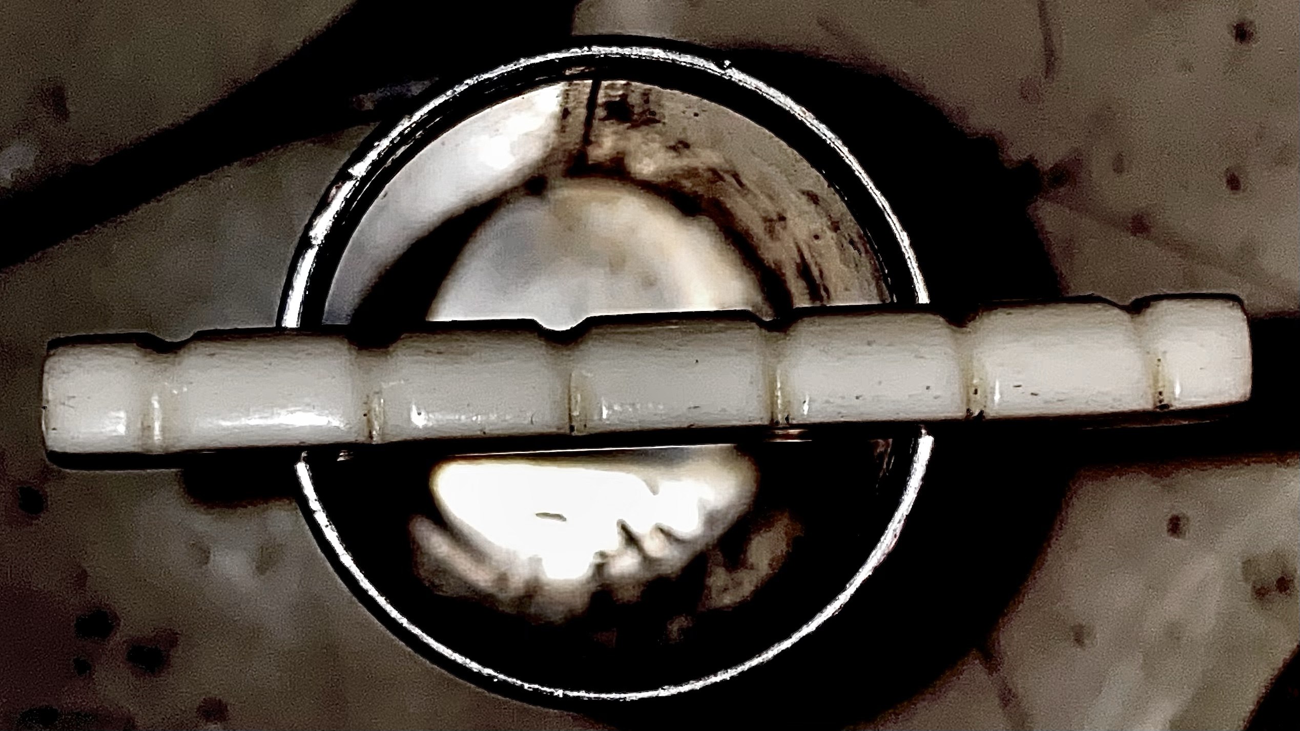
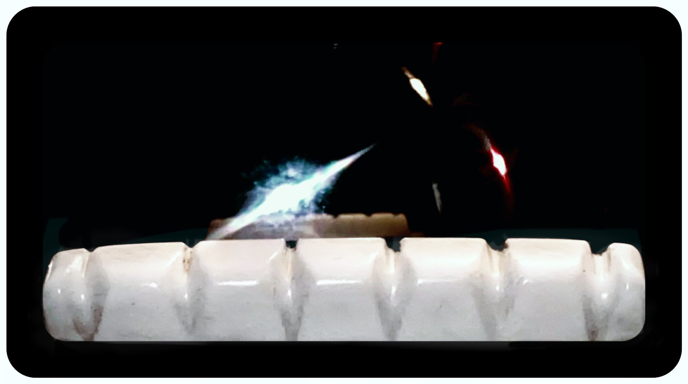
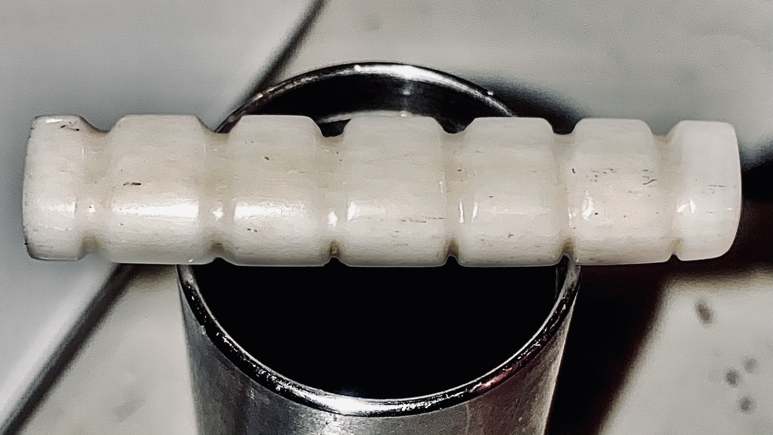
boner nut by fom tooley
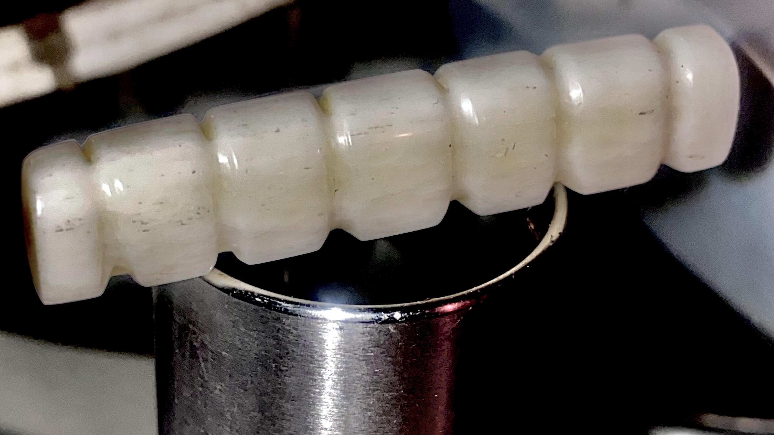
real handmade bone nut for acoustic snd classical guitars
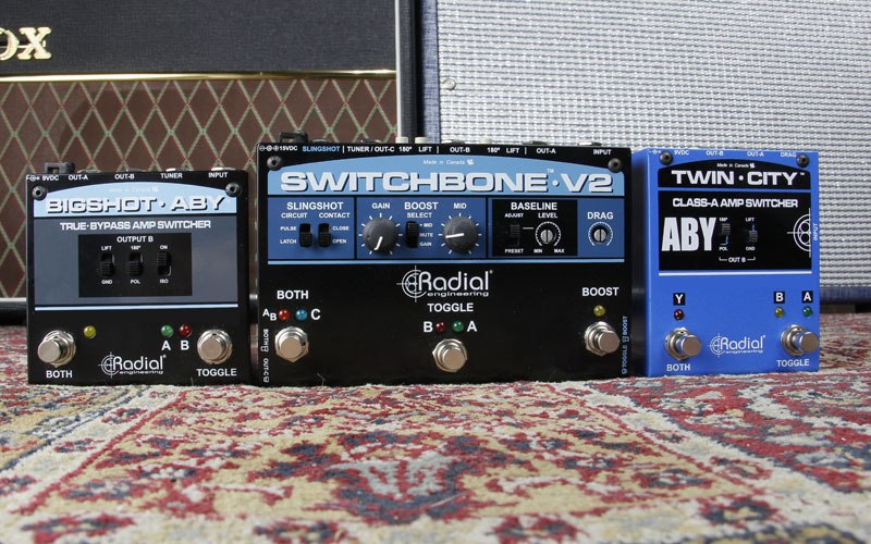
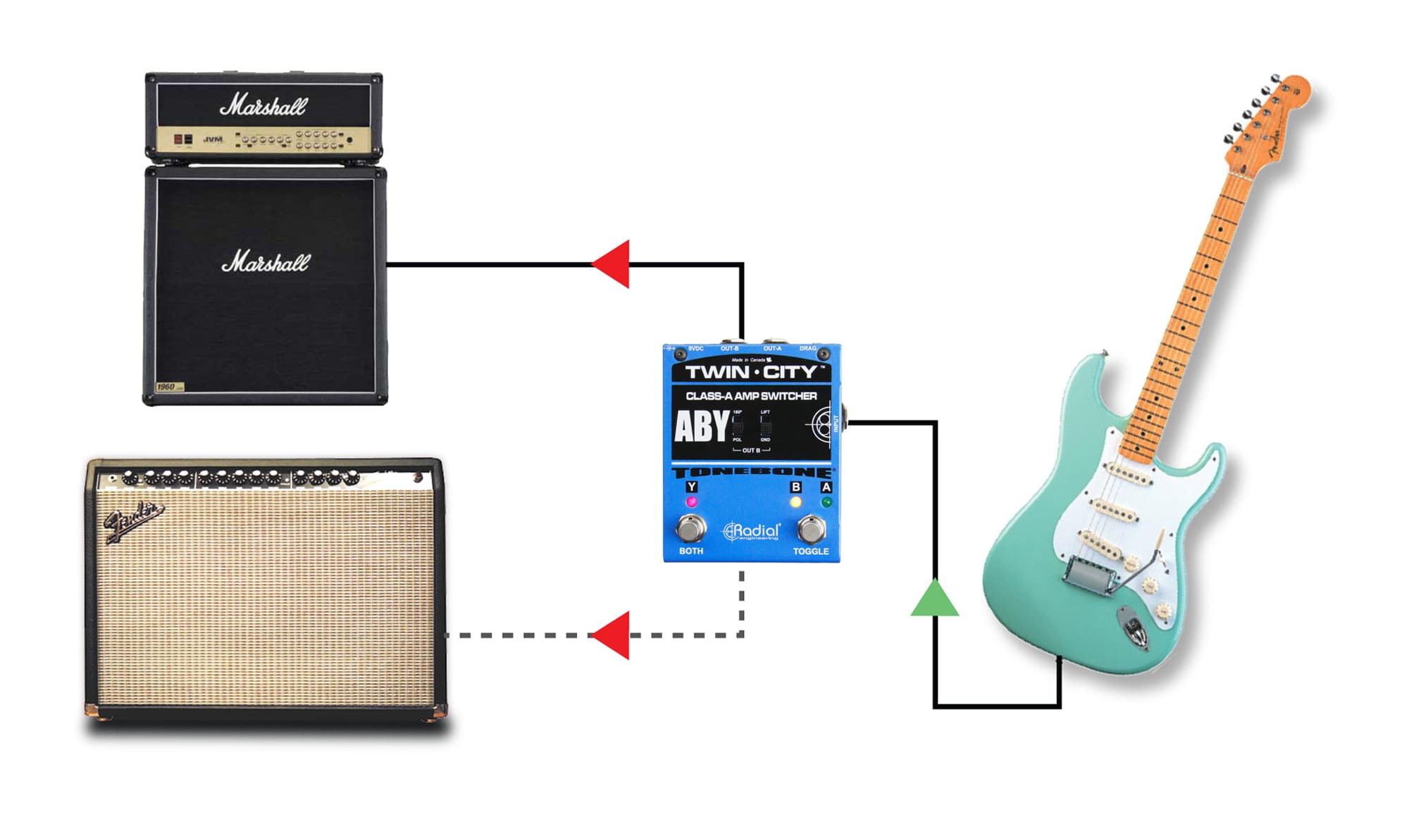
ABY switchers are primarily used to feed two guitar amps from a guitar. The AB designates the ability to switch between amplifiers, while the Y means that both amps can be turned on at once. Using an ABY switcher is easy. You connect your guitar or the output from your pedal chain to the ABY, and from the ABY, you feed the two amps. Unfortunately, the results often include tremendous noise, weird tones, and even an electrical shock.
ABY pedals generally come in two categories: passive and active. Passive ABYs do not require any power to make them work while active ABYs must be powered like most other guitar pedals.
Passive ABYs are simple switches that divert the guitar signal to one amp or the other. There is no ‘buffer’ or electronic amp inside the ABY to manage the signal. Some tone purists prefer passive switchers as they do not color the guitar signal in any way. When running two amps at once, the signal going to each amp is reduced by half, like a simple Y-jack cable. The BigShot ABY is a passive ABY switcher.
Active switchers employ a buffer or unity-gain amplifier to lower the impedance to reduce susceptibility to noise and manage the electrical signal. A buffer not only drives the signal further without noise, but the capacitors in the signal path also block noise that may be coming from the amp from bleeding back into the guitar.
Pedals that completely remove the effect circuit from the signal path are known as true-bypass pedals. The concept here is that a true-bypass pedal will relay the original sound of the guitar without any buffer or loading on the pickup which could alter the clean tone. The downside with true-bypass pedals is that they tend to produce switching noise. This is due to the hard contact that is created when the footswitch is depressed and the internal relay is called into action. The noise is most noticeable when using high-gain amps.
The benefit to using active switching with a buffered circuit is that it allows the electronic engineer to manage the signal to eliminate noise. The Twin-City employs electronic switching while the Switchbone employs a series of photo-electric chips (optocouplers) that ramp up and then ramp down the signal in a controlled fashion in order to eliminate the hard contact. This type of switching requires the signal to be buffered.
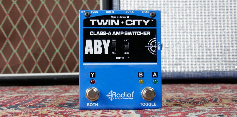
There are two general camps when it comes to buffers. The most common is the use of an integrated circuit (IC) while the second is more of an old-school discrete class-A approach. For maximum efficiency, ICs pack thousands of transistors inside a very small package to produce tremendous gain. To control the gain, various degrees of negative feedback is applied. Most guitarists hate the sound of these buffers as they make a nice warm-sounding guitar sound harsh. This is the primary reason guitarists complain about the sound of wireless systems. Both the Twin-City and the Switchbone employ 100% discrete, class-A circuitry. Instead of trying to control the gain of a chip by applying tremendous amounts of phase-canceling negative feedback, individual transistors are used at each gain stage. This means only the absolute minimal amount of negative feedback is applied. And because we are using class-A circuitry, you get a much purer signal path.
Early on, we discovered that even with the very best circuit, buffering a guitar signal can make it sound ‘too clean’. To solve the problem, Radial invented Drag Control – a simple load correction circuit that compensates for the overly clean signal path and replicates the tone as if connected directly to the amp. This encompasses compensating for the natural roll off of the cable and of course the load that is typically applied from a tube amp – whereby it sounds totally different from a transistor amp.
The hum and buzz caused by a so-called ground loop are produced when two amps are connected together and share both an electrical ground and an audio ground. The noise problem can be mild to acute depending on the amps, the electrical circuit and other factors such as spurious noise from the electrical system. The first line of defense is to connect both amps and all of the pedals to a single power strip. This ensures the same electrical phase is powering both amps. Unfortunately, more often than not, this solution rarely solves the problem that is inherent with varying voltage references and grounding schemes on the amps. To solve the problem, transformers are inserted into the audio path.
A typical transformer is a device that is made up of two coils and an inner core. The primary or input coil becomes magnetically charged when current is applied. The magnetic field is then transmitted through the core where it excites the secondary coil which in turn produces an electrical current. This creates a magnetic bridge that passes audio, while blocking stray DC currents and noise. Since the bridge is magnetic, there is no direct electrical connection. This disconnects the audio ground and breaks the ground loop, thus eliminating the hum and buzz. The Twin-City and Switchbone have transformers on output-B for this reason. The BigShot ABY also has a transformer that may be inserted into the signal path. As transformers are passive, you can lose some of the signal going through it unless the signal is first buffered by a pedal.
When playing two amps, it is important that they both play in phase. This means that both speakers are pushing outward instead of one going in, while the other goes out. When both amps are on, if the sound is distant, the amps are likely out of phase. In order to phase-align the amps, you must be able to reverse the polarity at the output of the ABY switcher. This requires a transformer. The BigShot ABY, Twin-City and Switchbone are equipped with transformers and 180º degree phase switches to invert the polarity.
As mentioned above, true-bypass switches are basically hard electrical switches produced by a footswitch or an electronic relay. These do not color nor load the pickup but do so at the expense of a loud pop. This is most noticeable when using high-gain or distorted amps. The BigShot ABY uses a true-bypass footswitch. Electronic switching as used in the Twin-City employs an electronic circuit to do the switching. This buffered circuit allows the engineer to control the switching to eliminate the loud pop. In this case, the buffered signal is always in the signal path. The Switchbone goes one step further by employing opto-couplers that ramp up and down the signal for a super smooth and quiet transition. Opto-couplers employ an internal light and receptor to do the work. These are expensive and rarely used.
To avoid an electric shock, never disconnect the U-ground on your guitar amps. This is sometimes done to eliminate noise. The ground is there for safety and will save your life if ever you find yourself on a wet stage or somehow get entangled in a situation where the power system from the lights or PA is at odds with your guitar amp setup.
The products mentioned in this article can all be purchased from Radial Engineering at: https://www.radialeng.com