- Ferrite core turns ratio calculation
- Push pull topology ferrite core turns ratio calculation with example
- Ferrite transformer primary turns calculation
- Ferrite transformer secondary turns calculation
In this article you will learn how to calculate turns ratio of ferrite core transformer for high frequency switch mode power supply inverters. High ferrite core transformers are used in almost every power electronics circuits like invertersand pure sine wave inverters. They are used to boost up or step up low dc voltage of battery and other dc sources like solar panels. Ferrite core transformers are also used in isolated dc to dc converters to step up or step down dc voltage. For example in isolated buck converter it is used to step down dc voltage and in isolated boost converter, they are used to step up dc voltage. In this article, we will learn how to calculate turns ratio of high frequency ferrite core transformer with examples.
Ferrite core turns ratio calculation
For example in boost up stage we have two options to use from power electronics converters, push pull topology and full bridge. I will explain both methods one by one. Turns ratio calculation formula and concept remains same for both topologies. The only difference between push pull topology and full bridge transformer design is that push pull ferrite core transformerrequires a center tap in primary winding. In other words, push pull transformer have two times primary turn than full bridge transformer.
Push pull topology ferrite core turns ratio calculation with example
Let’s start with example. For example we want to design a 250 watt boost up dc to dc converter. We are using push pull topology for this design. We are using 12 volt battery. We want to step up dc voltage from 12 volt 310 volt. Switching frequency of design is 50KHz. We are using ETD39 ferrite core which can handle 250 watt. It is beyond the scope of this topic to tell how to select ferrite core according to power rating. I will try to write separate article on it. The output of ferrite core will be always high frequency square wave of 50 KHz. We need to use full rectifier to convert it into dc of 310 volt. You may also need to use LC filter to harmonics or AC components from output.
Ferrite transformer primary turns calculation
As you know battery voltage does not remain same all the time. As the load on battery on increases, battery voltage will be less than 12 volt. With no load with fully charged battery, battery voltage will be near to 13.5 volt. Therefore input voltage is not constant, we must consider it while calculating turns ratio of ferrite core transformer. Cut off voltage for battery is usually 10.5 volt. We can take it as smallest possible value of input voltage to boost up dc converter. So we have following parameters now:
Vinput = 10.5 volt
Vout = 310 volt
As we know that formula of turns ratio calculation in transformer is
N = Npri / Nsc = Vin / Vout
Where Npri is number of primary turns and Nsc is number of secondary turns. We have three know variables like turns ratio which can be calculated by above equation, input voltage and output voltage. But we need to calculate primary turns to find secondary turn of ferrite core transformer. Formula to calculate primary turns for ferrite core transformer is given below:
Npri = Vin * 10^8 / 4 * f * Bmax * Ac
But for push pull it will be half the primary number of turns.
- Where Npi is primary number of turn, Vin( nom) is normal input voltage which in our example is 10.5 volt.
- Bmax is maximum flux density. The unit of maximum flux density is Guass. Remember if you are using Tesla unit for maximum flux density, IT = 10^4 Guass. The value of maximum flux density is usually given in data sheet ferrite core. We usually take value of Bmax between 1300G to 2000G. This is usually a acceptable range for all ferrite core transformers. Note : High value of flux density will saturate the core and low value of flux density will lead to core under utilization. For example we will take 1500G for dc to dc converter example.
- f is switching frequency converter. In our example switching frequency of dc to dc converter is 50 KHz.
- Ac is effective cross sectional area of ferrite core. We have to refer data sheet for this value. In this example, we are using ETD39 core. The effective cross sectional area of ETD39 is 125mm^2 or 1.25cm^2.
We have all the values to calculate primary number of turns .i.e.
Vin = 10.5 volt, Bmax = 1500G, f = 50 KHz, Ac = 1.25 cm^2
By putting these parameters in two above formula, we can calculate turns primary number of turns.
Npri = 12 . 10^8 / 4 . 50000 . 1500 . 1.25 = 3.2
Hence Npri = 3.2 But we cannot use fractional turns. So we need to round off primary turns calculated value into nearest whole number 3. The nearest possible whole number is 3. primary number of turns for ferrite core is 3. But before that we need check either for Npri = 3 Bmax is within acceptable range or not. As I have mentioned above the acceptable range for Bmaz is 1300-2000G. But the question is why we need to check the value of Bmax again? Because we adjust the value of primary turns from 3.2 to 3. So let’s calculate value of Bmax for Npri = 3 by using above forumla.
Bmax = Vin * 10^8 / 4 * f * Npri * Ac
Bmax = 12 * 10^8 / 5 * 50000 * 3 * 1.25 = 1600G
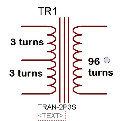
So calculated value of Bmax is 1600G which is within acceptable range of maximum flux density. Its mean we can take Npri = 3 for further calculations. Primary number of turns for push pull ferrite center tap transformer is 3 turns + 3 turns. In any design you will need to adjust the value of Npri if it is in fraction. You can easily adjust it. But you need to check value of Bmax every time. We start with assume value of Bmax and calculated Npri. But you can also start with assume value of Npri and check the value of maximum flux density Bmax. For example suppose a value of Npri =1 and check the value of Bmax and keep repeating this process, until it is become in acceptable range.
Ferrite transformer secondary turns calculation
Now let’s move to secondary turn of ferrite core. In our design the output of dc to dc converter is 310 volt at any input voltage. Input voltage is variable from 10.5 volt to 13.5 volt. We will need to implement
Feedback to get regulated 310 output voltage. So we will take little bit higher value of output voltage so that at minimum possible input we can still get output voltage of 310 volt by changing the duty cycle of PWM. So we should design a ferrite core transformer with secondary rated at 330 volt. Feedback will adjust the value of output voltage by changing the duty cycle of PWM. You should also take care of losses and voltage drops across switching devices and you should take them into account while designing transformer.
So transformer must be able to supply 330 volt output with input of 13.5 volt to 10.5 volt. The maximum duty cycle for PWM is 98% and rest 2% is left for dead time. During minimum possible input voltage duty cycle will be maximum. At maximum duty cycle of 98%, input voltage to transformer is 0.98 * 10.5 = 10.29 volt.
By using voltage ratio formula of transformer = voltage ratio = 330 / 10.29 = 32.1. Voltage ratio and turns ratio in transformer is equal to each other. Hence N = 32.
So we know all values to calculate secondary turns of ferrite core transformer.
N = 32, Npri = 3
Nsec = N * Npri = 32 *3 = 96
So number of primary turns is equal to 3 and number of secondary turns is equal to 96. So it is all about turns ratio calculation for high frequency transformers. If you have any issue, let me know with your comments.